Reverse Engineering Electronic Circuits: Tools, Techniques & Limitations
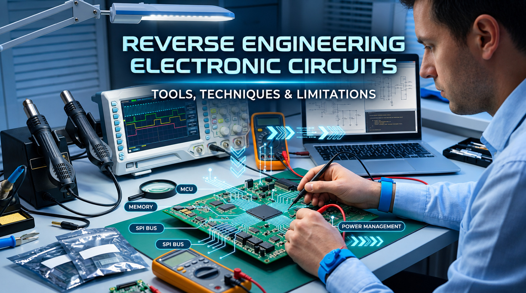
Learn how reverse engineering electronic circuits helps engineers analyze existing boards, understand their components and connections, recover design details, and recreate or improve electronic hardware when original documentation is unavailable.
Reverse engineering electronic circuits is the process of analyzing an existing product, circuit board, or electronic assembly to understand how it works, what parts it contains, how those parts are connected, and how the design can be documented or recreated.
This method is helpful when original blueprints are not available when parts are no longer made, when an old product needs to be improved or when an engineering team needs information. It is not, about making a copy of a board. The main aim is to get engineering details and check how the hardware acts.
For businesses dealing with electronics PCB reverse engineering can turn a board that has no information into a clear engineering guide. That guide can help with fixing, changing, making, updating, checking and creating products in the future.
What Is Reverse Engineering Electronic Circuits?
Reverse engineering electronic circuits is easier to manage when the investigation begins with a clear question: what must the team learn from the existing hardware?
In simple terms, reverse engineering electronic circuits means working backward from physical hardware to understand the circuit and its design.
Engineers inspect the board, identify components, trace electrical connections, study signals, reconstruct schematics, document the PCB structure, and test the recovered design. The depth of the work depends on the project objective and the condition of the hardware.
A finished product does not automatically reveal every design decision made by its original engineers. Some information may be visible, some may need measurement, and some may remain uncertain. Good reverse engineering therefore combines observation, measurement, documentation, and validation.
Looking for Help Understanding an Existing PCB?
In case you already have an existing PCB design, electronic product or circuit that lacks documentation, we can assist in the reverse engineering of the hardware.
Learn More about Reverse Engineering Services →
Why Do Companies Need Reverse Engineering Electronic Circuits?
A well-scoped reverse engineering electronic circuits project connects the physical evidence to a specific business or engineering need.
The scope of reverse engineering electronic circuits should match the intended outcome, whether that outcome is repair, documentation, redesign, or manufacturing support.
Companies usually need this work because important engineering information is missing, outdated, or difficult to recover.
A legacy controller may still perform an important job even though its original design files are gone. An obsolete sensor board may need a replacement component. A product team may need to redesign an old board without changing its external behavior. In each case, reverse engineering can provide a practical starting point.
Common reasons include:
- Recovering lost schematics and PCB documentation
- Understanding undocumented hardware
- Replacing obsolete or unavailable components
- Supporting repair and maintenance of legacy products
- Preparing an existing product for redesign
- Creating manufacturing documentation
- Investigating failures or unexpected behavior
- Comparing engineering choices between products
- Supporting product modernization
The goal should always be defined before the hardware is opened. A repair project needs different information from a full redesign project.
What Information Can Be Recovered From an Electronic Circuit?
A detailed review of reverse engineering electronic circuits focuses on recovering information that can be verified from the physical hardware.
A physical board can reveal much more than component names, but the available information depends on the board and the inspection method.
Typical outputs can include:
- Component identification and package information
- Component locations and reference designators
- Electrical connections and net relationships
- Reconstructed schematics
- PCB layer and routing information
- Netlists
- Bill of materials
- Connector and interface information
- Power distribution details
- Test and measurement results
- Functional behavior
- Manufacturing documentation
For example, identifying a microcontroller tells you what device is present, but it does not by itself explain every firmware function or software decision. Hardware and firmware should be treated as connected but separate engineering layers.
How Does Reverse Engineering Electronic Circuits Work?
In practical projects, reverse engineering electronic circuits starts with a clear scope so the team knows what evidence must be collected.
A reliable project normally follows a controlled sequence instead of immediately tracing every copper track.
1. Define the Objective
First decide what the project must deliver. The objective may be a schematic, a replacement PCB, component alternatives, a functional report, a manufacturing package, or a complete redesign reference.
2. Document the Original Hardware
Engineers photograph the board, record markings, document connectors, note physical dimensions, and preserve the original condition before invasive inspection.
3. Identify Components
Component markings, package types, datasheets, manufacturer information, and known electrical characteristics are compared to identify parts and likely alternatives.
4. Map Electrical Connections
Continuity measurements, visual inspection, layer analysis, and other techniques help determine which points are electrically connected.
5. Reconstruct the Schematic
The recovered connections are organized into an editable circuit representation. Power, ground, signal paths, interfaces, and functional blocks should be documented clearly.
6. Analyze the PCB
The board's physical layout, component placement, copper layers, vias, traces, connectors, and other construction details are recorded.
7. Test and Verify
The reconstructed information should be compared with actual hardware behavior. Measurements under controlled conditions can reveal whether the recovered design explains what the product actually does.
8. Prepare Documentation
The final deliverables should be organized so another engineer can understand, review, modify, or manufacture the recovered design.
Which Tools Are Used for Reverse Engineering Electronic Circuits?
The tools selected for reverse engineering electronic circuits depend on whether the project needs connectivity, signal, component, layer, or functional information.
The right tools depend on what needs to be discovered. No single instrument can reveal the entire design.
Digital Multimeter
A digital multimeter is useful for measuring voltage, resistance, continuity, and other basic electrical properties. It can help confirm connections and identify power rails, grounds, and simple circuit relationships.
Oscilloscope
An oscilloscope shows how an electrical signal changes over time. This makes it useful for examining clocks, switching behavior, communication signals, power-rail ripple, startup sequences, and transient events.
Logic Analyzer
A logic analyzer is useful when engineers need to inspect digital signals across multiple channels. It can help reveal timing and communication activity on interfaces such as SPI, I2C, UART, and other digital buses.
Bench Power Supply
A controlled power supply allows engineers to energize hardware while monitoring voltage and current. Current limits can also provide an additional layer of protection during controlled testing.
Microscope and Inspection Equipment
Small packages, solder joints, markings, vias, trace geometry, and board damage can be difficult to inspect with the naked eye. Optical inspection helps engineers document these details before making measurements.
X-Ray and Advanced Imaging
Imaging methods can provide additional information when components or connections are hidden. They can be especially useful for complex assemblies where visual inspection cannot reveal the complete construction.
EDA and PCB Software
Electronic design automation tools help engineers draw reconstructed schematics, manage components, create netlists, document board layers, and prepare editable engineering files.
How Does PCB Reverse Engineering Work on Multilayer Boards?
For difficult boards, reverse engineering electronic circuits may require several inspection methods rather than one measurement technique.
Multilayer boards require more analysis because some copper connections are hidden between the visible surfaces.
A two-layer board can often be inspected more directly. A multilayer board may contain internal power planes, signal layers, buried connections, vias, and dense routing that cannot be understood from the top and bottom surfaces alone.
Engineers may combine high-resolution imaging, continuity mapping, layer analysis, component identification, and controlled electrical testing. The aim is to build a consistent picture of how the board is constructed and how its electrical networks connect.
This is one reason PCB reverse engineering should not be treated as simple tracing. A trace that disappears into a via has not disappeared from the circuit; it may continue on another layer or connect to an internal plane.
What Techniques Are Used in PCB Reverse Engineering?
The strongest reverse engineering electronic circuits projects combine several techniques and cross-check the results before documentation is finalized.
Several techniques work together during board analysis.
Visual Inspection
The first step is usually careful observation. Engineers document component markings, package types, connectors, mounting features, visible traces, test points, damage, and manufacturing details.
Continuity Mapping
Continuity measurements help establish whether two physical points are electrically connected. Repeating these measurements across relevant nets can help reconstruct relationships that are not obvious visually.
Datasheet Cross-Referencing
Once a component is identified, its datasheet can provide pin functions, package information, electrical limits, typical application circuits, and other useful context. This helps explain why a group of connections may exist.
Layer Analysis
Layer-by-layer analysis becomes important when the board contains hidden routing or planes. The recovered layer information can be organized into a PCB design environment for further review.
Functional Testing
Measurements during operation help connect the physical circuit to its real behavior. Engineers can observe power-up sequences, signal timing, interface activity, sensor outputs, and other measurable functions.
Schematic Reconstruction
Recovered electrical relationships are organized into a logical schematic. This makes the design easier to review than a collection of photographs and continuity measurements.
Netlist Extraction
A netlist describes electrical connectivity between components or pins. It can be useful for comparing reconstructed connectivity with the physical board and for supporting later PCB work.
Working with an Undocumented or Outdated PCB?
Rhosigma can assist you in identifying components, schematics reconstruction, analysis of PCBs, creation of a netlist, function verification, and engineering documentation of existing electronics hardware.
Discuss Your Reverse Engineering Project →
What Are the Main Limitations?
Understanding the limits of reverse engineering electronic circuits helps teams set realistic deliverables before analysis begins.
Reverse engineering has limits. A physical product does not always preserve every piece of information from the original development process.
Hidden Layers
Internal PCB layers may require advanced inspection methods. Some structures can be difficult to recover without specialized equipment or destructive analysis.
Damaged Hardware
A burned, corroded, cracked, or heavily modified board can hide important evidence. Engineers may need to combine measurements with component datasheets, comparable circuits, and functional testing.
Missing Component Markings
Some components have faded, removed, custom, or unreadable markings. Identification then becomes a process of comparing package characteristics, surrounding circuitry, electrical behavior, and available documentation.
Firmware Limitations
Hardware analysis does not automatically recover source code. A microcontroller may contain protected, encrypted, or otherwise inaccessible firmware. Hardware reconstruction and firmware recovery are separate tasks.
Unknown Design Intent
Even after a circuit is mapped correctly, the original reason for every design choice may not be known. Engineers can document observable behavior and likely functions, but should distinguish verified facts from engineering interpretation.
Is Reverse Engineering the Same as Copying a PCB?
The distinction becomes important when reverse engineering electronic circuits is being used to support a redesign rather than a direct reproduction.
No. Reverse engineering is broader than copying the physical shape of a board.
A copy may reproduce dimensions and visible features. A proper engineering investigation tries to understand the circuit, components, electrical connections, functionality, manufacturing details, and documentation needed for the project.
The difference matters when a company wants to modernize a legacy product. The goal may be to preserve the product's behavior while changing obsolete components, improving reliability, reducing cost, or adapting the design to current manufacturing requirements.
How Can Reverse Engineering Help With Legacy Electronics?
For legacy products, reverse engineering electronic circuits can recover enough engineering information to create a controlled path toward modernization.
Legacy electronics often create a difficult business problem: the product still works, but the documentation, components, or original engineering team may no longer be available.
Reverse engineering can create a structured engineering baseline from the existing hardware. Once the design is documented, teams can investigate component alternatives, redesign selected sections, create replacement boards, or plan product upgrades.
For example, an obsolete controller may be analyzed to recover its schematic, identify unavailable components, document interfaces, and understand operating behavior. The recovered information can then support a controlled redesign rather than forcing the team to start from zero.
What Should You Provide Before Starting a Reverse Engineering Project?
Before starting reverse engineering electronic circuits, the project team should identify the available hardware, documentation, and expected deliverables.
The more useful information available at the beginning, the easier it is to define the right scope.
Useful inputs include:
- Physical PCB or complete product
- Clear photographs
- Existing schematics, drawings, or manuals
- Firmware files, when legally available
- Previous BOMs or component lists
- Product specifications
- Known operating conditions
- Failure symptoms, if the project involves troubleshooting
- Required final deliverables
- Any confidentiality or intellectual-property requirements
If no documentation exists, that does not automatically stop the project. The physical hardware itself can become the primary source of engineering information.
How Does Rhosigma Approach Electronic Reverse Engineering?
Rhosigma applies a structured approach to reverse engineering electronic circuits, combining information extraction, analysis, reconstruction, verification, and documentation.
Rhosigma approaches reverse engineering as a structured engineering process rather than a simple teardown.
Its published workflow covers requirement and scope definition, information extraction, teardown and disassembly, scanning and modeling where needed, component and material analysis, circuitry and design reconstruction, review and verification, and documentation transfer.
For electronic hardware, Rhosigma describes capabilities including schematic reconstruction, netlist extraction, layer-by-layer PCB analysis, component identification, datasheet cross-referencing, BOM generation, and functional verification.
This approach is useful when a company has a physical PCB but incomplete engineering documentation. The recovered information can then support redesign, manufacturing, component replacement, or future product development.
When Should You Choose Professional Reverse Engineering Services?
For complex projects, professional reverse engineering electronic circuits can reduce uncertainty by combining measurement, documentation, and engineering review.
Professional engineering support becomes useful when the board is complex, the documentation is missing, the hardware is valuable, or the final output must be reliable enough for further development.
It is especially relevant for:
- Multilayer PCBs
- Legacy industrial electronics
- Obsolete products
- Complex embedded systems
- Missing schematic and PCB files
- Component obsolescence projects
- Product redesign
- Manufacturing documentation recovery
- Hardware validation and comparison
The most important question is not simply whether a board can be analyzed. It is whether the recovered information will be accurate and useful for the next engineering step.
What Are the Most Important Things to Remember?
The key principles of reverse engineering electronic circuits are evidence, traceability, verification, and clear documentation.
Reverse engineering electronic circuits is an evidence-based engineering process.
A physical board can reveal components, connections, construction, and behavior, but not necessarily the complete original design intent. Good documentation and verification are therefore just as important as the initial inspection.
Ten practical points are worth remembering:
- A physical PCB does not automatically reveal the complete original design.
- Multimeters and oscilloscopes provide different types of electrical information.
- Multilayer boards require additional analysis because important connections may be hidden.
- Component identification should be checked against reliable technical information.
- A reconstructed schematic should be validated against the physical hardware.
- Firmware and hardware should be analyzed as separate but related engineering layers.
- Functional testing can reveal information that visual inspection cannot.
- Good documentation makes recovered engineering knowledge reusable.
- Reverse engineering can support redesign and modernization, not only replication.
- Legal, ethical, confidentiality, and intellectual-property requirements should be considered before starting a project.
Need an Electronic Product to Be Reconstructed?
If you have a legacy PCB, missing design documents, obsolete parts, or any undocumented electronic product, Rhosigma is there to help you know what can be retrieved and how the next step in engineering process should look like.
Conclusion
Reverse engineering electronic circuits provides a practical way to recover engineering knowledge from existing hardware. It can help companies understand undocumented products, maintain legacy electronics, replace obsolete components, reconstruct lost design files, and prepare products for redesign.
The process combines physical inspection, electrical measurement, component research, PCB analysis, schematic reconstruction, functional testing, and documentation. For simple boards, the work may be relatively straightforward. Complex multilayer and embedded systems require a more structured approach.
PCB reverse engineering is therefore not just about tracing copper tracks. It is about building a reliable engineering picture of how the hardware is constructed, connected, and expected to behave.
When the recovered information will be used for repair, redesign, manufacturing, or product modernization, accuracy matters. A properly documented reverse-engineering project gives engineers a clearer foundation for making the next design decision.
FAQs
What is reverse engineering electronic circuits?
Reverse engineering electronic circuits is the process of analyzing an existing electronic product or PCB to understand its components, electrical connections, functionality, and design. The recovered information can support documentation, repair, redesign, modernization, or manufacturing.
What tools are used for reverse engineering electronic circuits?
Common tools include digital multimeters, oscilloscopes, logic analyzers, bench power supplies, microscopes, imaging equipment, and EDA or PCB design software. The exact tools depend on the hardware and the information that needs to be recovered.
What is PCB reverse engineering?
PCB reverse engineering is the process of analyzing an existing printed circuit board to recover information such as components, connections, layer structure, netlists, schematic information, and layout details. The work can support repair, redesign, documentation, or manufacturing.
Can a PCB be reverse engineered without the original schematic?
Yes. Engineers can work from the physical board by identifying components, tracing connections, analyzing layers, measuring electrical behavior, and reconstructing the schematic. The amount of information that can be recovered depends on the board's condition and construction.
What are the limitations of reverse engineering electronic circuits?
Limitations can include hidden PCB layers, damaged hardware, missing component markings, inaccessible firmware, encrypted devices, and uncertainty about the original design intent. Testing and multiple inspection methods can reduce uncertainty, but they cannot guarantee recovery of every original design detail.
When should a company use professional reverse engineering services?
Professional support can be useful when original design files are missing, components are obsolete, the board is multilayer or complex, or the recovered information will be used for redesign or manufacturing. An experienced engineering team can also help define the scope and deliverables before detailed analysis begins.