Reverse Engineering in Mechanical Design: Rebuilding Legacy Components
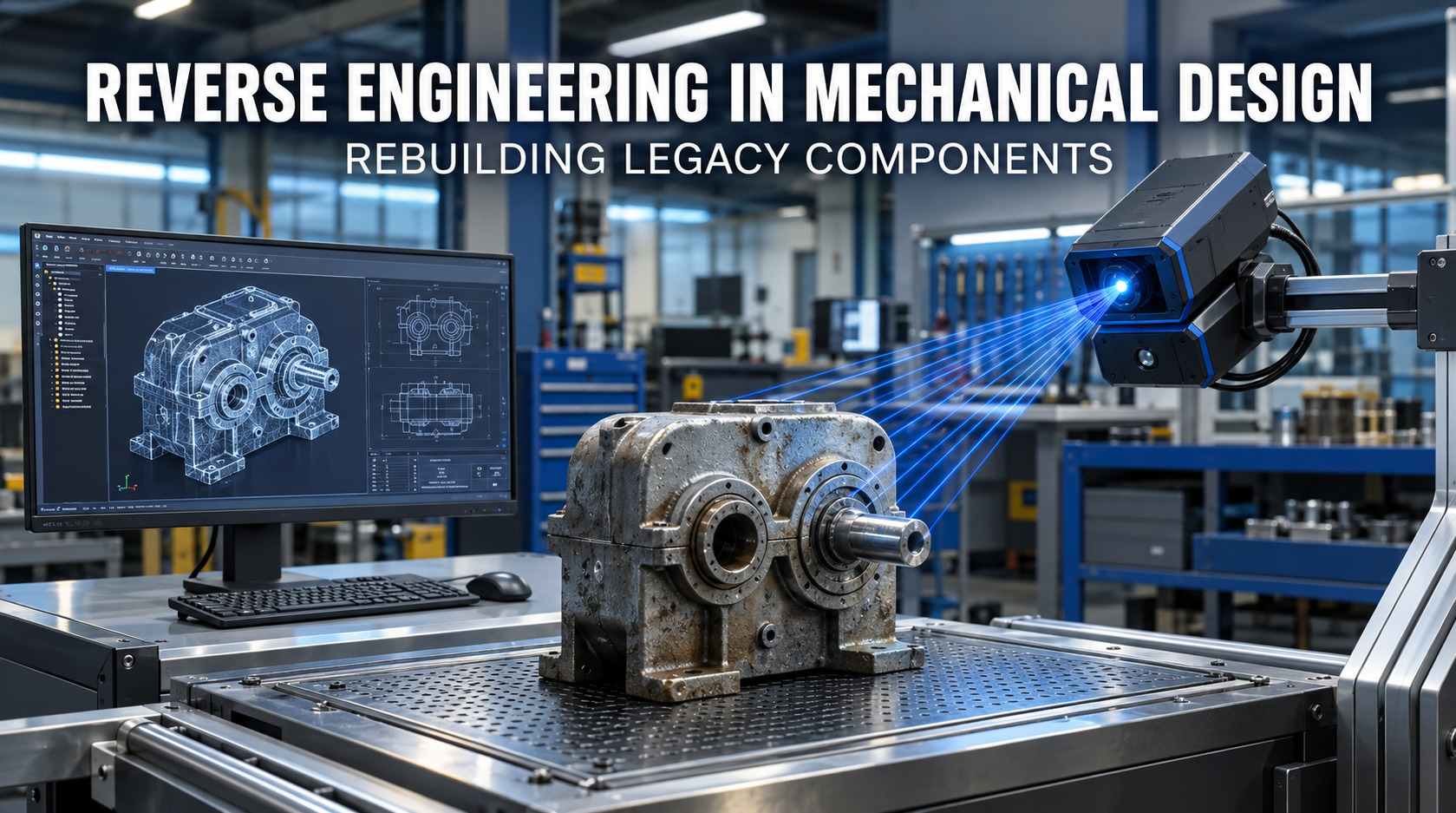
Learn how reverse engineering turns existing mechanical parts into accurate CAD models, engineering data, and manufacturing-ready designs.
When a machine part has been used for years the original computer-aided design files, drawings, details or manufacturing information might not be around anymore. The original company that made the part might no longer exist the machine might be out of date. The engineers who created the part might not be working anymore.
In these cases reverse engineering in mechanical design offers a good way to get important engineering details from a real part.
Instead of designing a replacement entirely from scratch, engineers can examine the real part, measure its size and shape, identify its material and functional characteristics, rebuild the design in CAD software, and validate the resulting model.
For businesses that have machines and products reverse engineering in mechanical design can turn a real part into useful digital engineering details.
What Is Reverse Engineering in Mechanical Design?
Reverse engineering in mechanical design is the process of looking at an existing physical part to get back its shape, size, materials, connections, how it works and other important engineering details.
The physical component becomes the starting point for rebuilding its digital engineering definition.
Depending on the project, the final deliverables may include:
- 3D CAD models
- Parametric CAD models
- 2D engineering drawings
- Dimensional information
- Material specifications
- Assembly information
- Inspection reports
- Manufacturing recommendations
- Redesign concepts
- Prototype data
The objective is not simply to reproduce the visible shape of a component. Engineers must also understand how the part functions, how it connects with other components, what loads it experiences, and how it can be manufactured reliably.
This is why reverse engineering in mechanical design involves both physical measurement and engineering interpretation.
Why Do Engineers Reverse Engineer Legacy Mechanical Parts?
Companies often use reverse engineering in mechanical design when important engineering information is missing, outdated, or no longer accessible.
Common situations include:
- Original CAD files are unavailable.
- Engineering drawings are incomplete or damaged.
- The original manufacturer has discontinued the component.
- A supplier no longer supports an older machine.
- A replacement part is difficult to source.
- An existing component repeatedly fails.
- Production needs to be transferred to a new supplier.
- An old product needs to be redesigned or modernized.
- A physical prototype exists without a digital model.
- Existing documentation does not accurately represent the current component.
For example, consider a mounting bracket inside an older industrial machine. The bracket has cracked, but the manufacturer no longer supplies it and the original drawing cannot be found.
Instead of redesigning the bracket based on assumptions, engineers can inspect the existing component, measure its critical features, determine the material and manufacturing requirements, reconstruct the CAD model, and create a replacement drawing.
This approach allows reverse engineering in mechanical design to support manufacturing continuity while preserving important information from the original component.
Is Reverse Engineering the Same as Copying a Mechanical Part?
No. Reverse engineering in mechanical design involves much more than copying the external shape of a component.
A proper engineering reconstruction considers factors such as:
- Material grade
- Wall thickness
- Hole sizes and locations
- Tolerances
- Surface finish
- Fillet radii
- Heat treatment
- Fastener interfaces
- Load direction
- Manufacturing process
- Assembly requirements
- Functional surfaces
A 3D scanner can capture the physical geometry of a component, but the resulting scan does not automatically become a production-ready engineering drawing.
Engineers still need to interpret the data and determine which dimensions, tolerances, datums, interfaces, and features are important to the component's function.
This distinction matters because a component can appear geometrically correct while still failing in operation if its material, tolerance, fit, or structural requirements are incorrect.
How Does the Reverse Engineering Process Work?
A typical reverse engineering in mechanical design workflow follows these stages:
Inspection → Measurement → 3D Scanning → CAD Reconstruction → Material and Functional Analysis → Design Review → Redesign → Prototype → Testing → Manufacturing
The exact process depends on the component, its condition, and the intended outcome.
1. Physical Inspection
The process begins with a detailed inspection of the existing component.
Engineers examine its overall condition and identify:
- Wear
- Cracks
- Deformation
- Corrosion
- Surface damage
- Broken features
- Fastener locations
- Mating surfaces
- Manufacturing marks
The condition of the part is important because worn or damaged areas may not represent the original design.
2. Measurement and Dimensional Capture
Critical dimensions are measured using appropriate inspection equipment.
Depending on the component, engineers may capture:
- Overall dimensions
- Hole diameters
- Center-to-center distances
- Thicknesses
- Radii
- Angles
- Clearances
- Shaft diameters
- Mounting interfaces
Not every visible dimension needs to become a CAD dimension. Engineers identify the measurements that are important to the component's function and manufacturing requirements.
3. 3D Scanning and Point-Cloud Data
For complex geometry, 3D scanning can provide a detailed digital representation of the physical surface.
The scanner produces point-cloud or mesh data representing the measured geometry.
However, scan data is not automatically a fully editable parametric CAD model. Engineers may need to clean the scan, align the data, identify important features, and remodel the component using appropriate CAD features.
This step is particularly useful when the part contains complex curves, organic surfaces, irregular geometry, or difficult-to-measure areas.
4. CAD Reconstruction
After measurements and scan data have been reviewed, engineers reconstruct the component in CAD.
The model may contain:
- Sketches
- Extruded features
- Revolved features
- Holes
- Fillets
- Chamfers
- Patterns
- Surfaces
- Assemblies
Where appropriate, the model is created parametrically so that important dimensions can be modified later.
The final CAD model should represent engineering intent rather than simply reproducing every irregularity visible on the scanned component.
A properly structured model makes reverse engineering in mechanical design more useful because the recovered design can be modified and reused for future engineering work.
5. Material and Functional Analysis
Geometry alone does not fully define a mechanical component.
Engineers may need to investigate:
- Material composition
- Hardness
- Heat treatment
- Surface coating
- Corrosion
- Wear
- Operating temperature
- Expected loading
- Contact conditions
For example, if a shaft has failed near a shoulder, the investigation may consider whether the material, fillet radius, loading condition, alignment, or surface condition contributed to the failure.
6. Design Review and Redesign
Once the original design has been reconstructed, engineers can evaluate whether it should simply be reproduced or improved.
Potential improvements include:
- Increasing strength
- Reducing unnecessary weight
- Improving manufacturability
- Improving assembly
- Increasing service life
- Improving access for maintenance
- Correcting known failure points
This stage allows reverse engineering in mechanical design to become a starting point for engineering improvement rather than simply a reproduction exercise.
7. Prototype and Testing
A prototype may be produced before full-scale manufacturing.
Depending on the application, engineers can evaluate:
- Fit
- Assembly
- Dimensions
- Function
- Structural performance
- Interference
- Thermal behavior
- Durability
Testing provides an opportunity to identify problems before the redesigned component enters production.
8. Manufacturing and DFM Review
The final design should also be reviewed for manufacturability.
Design for Manufacturing (DFM) considers whether the component can be produced efficiently using the selected manufacturing process.
The review may identify issues involving:
- Tool access
- Machining operations
- Material availability
- Wall thickness
- Bend radii
- Tolerances
- Surface finish
- Production cost
How Is a Physical Part Converted Into a CAD Model?
One of the main outcomes of reverse engineering in mechanical design is the conversion of a physical component into usable CAD data.
The process combines dimensional measurements, scan data, engineering interpretation, and feature-based modeling.
For simple components, engineers may recreate the geometry directly from measurements and sketches.
For complex components, the workflow may involve:
- Capturing scan or measurement data.
- Cleaning and aligning the data.
- Identifying important geometric features.
- Creating reference planes and datums.
- Rebuilding sketches and profiles.
- Creating solid or surface features.
- Adding holes, fillets, chamfers, and patterns.
- Checking the CAD model against the physical part.
- Creating the required engineering documentation.
Common exchange formats such as STEP and IGES can help transfer geometry between different CAD systems.
A properly structured parametric model also makes future modifications easier because important dimensions and relationships can be edited without rebuilding the entire component.
What Should Engineers Look for Beyond Geometry?
The most important information is not always visible from the outside of a component.
Engineers should also consider:
- What does the component do?
- What loads does it experience?
- Which surfaces must remain accurate?
- How does it connect to other parts?
- What material is required?
- What manufacturing process was originally used?
- Which features affect strength?
- Which dimensions affect assembly?
- What caused previous failures?
A major objective of reverse engineering in mechanical design is to understand the engineering purpose behind the geometry.
Consider a shaft that repeatedly develops cracks near a shoulder. Simply reproducing the existing geometry may reproduce the same failure.
A better approach is to investigate the loading, stress concentration, material, heat treatment, surface condition, and fillet radius before deciding whether the geometry should remain unchanged.
How Does Reverse Engineering Lead to Better Mechanical Design?
Reverse engineering in mechanical design can provide engineers with a detailed understanding of an existing component before they modify it.
Once the original geometry and functional requirements are understood, engineers can evaluate opportunities to improve:
- Strength
- Weight
- Material usage
- Manufacturability
- Assembly
- Maintenance
- Reliability
- Service life
For example, a heavy machined bracket may be redesigned with optimized geometry and appropriate reinforcement while maintaining its mounting interfaces.
The goal is not to change the design unnecessarily. Instead, engineers can preserve the features that are essential to the original function while improving areas that create cost, performance, or reliability problems.
What Are Some Reverse Engineering Examples in Mechanical Engineering?
Example 1: Obsolete Industrial Machine Bracket
An industrial machine uses a bracket that is no longer available from the original supplier.
Engineers inspect the existing bracket, measure its mounting interfaces, reconstruct the CAD model, identify the material and manufacturing method, and create a replacement drawing.
If the original bracket has experienced repeated cracking, the design can also be evaluated and modified before manufacturing the replacement.
Example 2: Legacy Pump Housing Component
A pump component may have complex internal and external geometry while the original drawings are unavailable.
3D scanning and dimensional inspection can help capture the physical geometry. Engineers can then reconstruct the CAD model and verify critical interfaces.
Material and functional analysis can also help determine whether the replacement should reproduce the original specification or use an updated material or design.
Example 3: Undocumented Product Enclosure
A company may have a physical enclosure for an older electronic product but no usable CAD data.
The enclosure can be measured or scanned, reconstructed in CAD, and updated to accommodate new internal components.
The resulting model can support further product development and manufacturing.
How Does Reverse Engineering Help With Components?
The output of reverse engineering in mechanical design can support a complete digital engineering workflow:
Physical Part → Inspection → CAD Model → Engineering Drawing → Prototype → Validation → Production
This process is particularly valuable for legacy components because it helps convert physical engineering knowledge into reusable digital information.
Once the component has been digitally reconstructed, the CAD data can support future modifications, supplier communication, manufacturing, inspection, and product development.
What Role Does Material Analysis Play in Reverse Engineering?
Material selection can have a major effect on component performance.
Material analysis may consider:
- Chemical composition
- Hardness
- Heat treatment
- Surface condition
- Coatings
- Corrosion
- Wear
- Thermal requirements
For a replacement component, matching the original material may be appropriate in some cases. In other situations, an improved material may be considered based on operating conditions and performance requirements.
Material decisions should therefore be based on the function and application of the component rather than appearance alone.
Can Reverse Engineering Include Failure Analysis?
Yes. Reverse engineering in mechanical design can be combined with failure analysis when an existing component has failed or shows signs of abnormal wear.
Engineers may examine:
- Crack locations
- Deformation
- Wear patterns
- Fracture surfaces
- Contact marks
- Fastener damage
- Corrosion
- Heat-related damage
The objective is to understand what happened and determine whether the component's design, material, manufacturing process, assembly, or operating conditions contributed to the failure.
The findings can then be used to improve the replacement design.
How Do FEA and Engineering Analysis Fit Into Reverse Engineering?
Finite Element Analysis (FEA) can be used after the component has been reconstructed to evaluate its behavior under defined loading and boundary conditions.
In reverse engineering in mechanical design, engineers may use FEA to investigate:
- Stress
- Deformation
- Structural strength
- Load distribution
- Reinforcement requirements
- Weight reduction opportunities
FEA does not replace physical testing, and its accuracy depends on the quality of the geometry, material properties, loading assumptions, and boundary conditions.
When used appropriately, it can help engineers compare the existing design with proposed improvements before committing to production.
Why Is DFM Important After Reverse Engineering?
A CAD model may accurately represent a physical component but still be difficult or expensive to manufacture.
DFM helps ensure that the reconstructed or redesigned component is practical for the selected manufacturing process.
CNC Machining
Engineers may review tool access, machining operations, internal corners, tolerances, and material removal.
Sheet Metal Fabrication
Important considerations can include bend radii, material thickness, bend sequence, hole locations, and manufacturability.
Injection Molding
The design may require appropriate wall thickness, draft angles, ribs, bosses, and considerations for tooling.
Additive Manufacturing
Engineers may evaluate build orientation, support requirements, wall thickness, overhangs, and material behavior.
The manufacturing process should therefore be considered during design rather than only after the CAD model is complete.
How Can Reverse Engineering Support New Product Development?
Reverse engineering in mechanical design can also support the development of new products.
A typical workflow may look like:
Existing Product → Design Recovery → Engineering Analysis → Requirements Definition → Redesign → Prototype → Testing → Manufacturing
An existing product can provide useful information about dimensions, interfaces, user requirements, manufacturing methods, and functional performance.
Engineers can then use that information to develop an updated product while addressing known limitations in the original design.
How Does Reverse Engineering Connect With Rhosigma's Engineering Services?
Rhosigma provides engineering and product-development support that can connect reverse engineering in mechanical design with downstream design and manufacturing activities.
Depending on project requirements, the workflow can extend from physical inspection and CAD reconstruction to mechanical design, analysis, prototyping, testing, and manufacturing support.
This integrated approach is useful when a company needs more than a digital copy of an existing component and wants to develop a manufacturable and validated engineering solution.
Need help converting an existing mechanical component into usable engineering data?
Explore RhoSigma's Reverse Engineering Services
When Should a Company Consider Reverse Engineering a Legacy Component?
A company should consider reverse engineering in mechanical design when important design information is unavailable or when an existing component needs to be understood before replacement or improvement.
Typical situations include:
- An original part is discontinued.
- CAD files are missing.
- Drawings are incomplete.
- A supplier is no longer available.
- A machine must remain operational.
- A component needs redesign.
- A new supplier needs manufacturing information.
- A product needs modernization.
- A component repeatedly fails.
- A physical prototype has no digital model.
Before starting, the project objective should be clearly defined.
The goal may be replacement manufacturing, redesign, cost reduction, supplier transfer, failure investigation, or product modernization.
What Deliverables Can Come From Mechanical Reverse Engineering?
The deliverables from reverse engineering in mechanical design depend on the project requirements.
They may include:
- 3D CAD model
- Parametric CAD model
- 2D engineering drawing
- Dimensioned drawings
- STEP or IGES files
- Assembly model
- Bill of Materials (BOM)
- Material information
- Measurement report
- Inspection data
- Scan or mesh data
- Failure analysis
- Manufacturing recommendations
- DFM observations
- Prototype information
- Test results
The required deliverables should be defined at the beginning of the project so the reconstruction process captures the information needed for its intended use.
What Are the Biggest Mistakes in Reverse Engineering Mechanical Parts?
Several mistakes can reduce the value of a reconstruction project.
1. Copying Worn Geometry
A damaged or worn surface may not represent the original design.
2. Ignoring Material Requirements
Using the wrong material can change strength, durability, wear resistance, and operating performance.
3. Ignoring Tolerances
A component can have correct nominal dimensions and still fail to assemble or operate correctly if tolerances are unsuitable
4. Skipping Validation
A CAD model should be checked against the physical component and, where necessary, validated through analysis or testing.
5. Designing Without Manufacturing Constraints
A technically correct CAD model may still be expensive or impractical to manufacture.
6. Recreating Known Design Failures
If an existing component has repeatedly failed, simply reproducing it may carry the same weakness into the replacement.
The purpose of reverse engineering in mechanical design should therefore be to recover useful engineering information, not blindly reproduce every characteristic of the existing part.
What Is the Future of Legacy Component Reconstruction?
As companies modernize older equipment and products, converting physical engineering information into digital data becomes increasingly important.
A physical component can contain valuable information about geometry, interfaces, materials, manufacturing methods, and functional requirements.
When that information is captured and organized into usable digital engineering data, reverse engineering in mechanical design can support:
- Product modernization
- Manufacturing continuity
- Supplier transfer
- Design improvements
- Digital documentation
- Maintenance
- New product development
This approach provides a practical connection between legacy physical products and modern digital engineering workflows.
Final Takeaway: Reverse Engineering Should Be the Beginning, Not the End
A physical mechanical component can contain far more information than its visible shape suggests.
A well-planned reverse engineering in mechanical design project can recover geometry, dimensions, material information, functional requirements, and manufacturing knowledge. That information can then be transformed into CAD models, drawings, analysis, prototypes, and improved designs.
For companies dealing with discontinued components, missing engineering documentation, obsolete machinery, or legacy products, reverse engineering in mechanical design can provide a structured path from an existing physical part to usable engineering data.
The most effective projects do not stop at creating a CAD model. They use the recovered information to understand the original design, validate its performance, identify opportunities for improvement, and create a practical path toward manufacturing.
Frequently Asked Questions
What is reverse engineering in mechanical design?
Reverse engineering in mechanical design is the process of analyzing an existing physical component to recover its geometry, dimensions, materials, interfaces, and functional requirements so the design can be documented, reproduced, analyzed, or improved.
Why is reverse engineering used for legacy mechanical parts?
It is commonly used when original CAD files, drawings, suppliers, or manufacturing information are unavailable and a company needs to replace, redesign, manufacture, or modernize an existing component.
Is reverse engineering the same as copying a part?
No. A proper engineering reconstruction considers geometry as well as materials, tolerances, interfaces, loads, manufacturing requirements, and functional performance.
Can 3D scanning be used for mechanical reverse engineering?
Yes. 3D scanning can capture complex physical geometry and create point-cloud or mesh data. Engineers then process and interpret this information to develop an appropriate CAD model.
Can reverse engineering improve an existing component?
Yes. Once the original component is understood, engineers can evaluate opportunities to improve strength, weight, manufacturability, assembly, reliability, or service life.
What are some examples of reverse engineering in mechanical engineering?
Common examples include reconstructing obsolete machine brackets, pump components, shafts, housings, enclosures, tooling, and other legacy components for replacement or redesign.
Does reverse engineering include material analysis?
It can. Depending on the project, engineers may investigate material composition, hardness, heat treatment, coatings, corrosion, wear, and other material characteristics.
Can reverse engineering support manufacturing?
Yes. The resulting CAD models, drawings, dimensional information, material requirements, and DFM recommendations can support prototype development, supplier transfer, and production manufacturing.
What is the difference between reverse engineering and redesign?
Reverse engineering focuses on understanding and recovering information from an existing product or component. Redesign uses that understanding to intentionally modify the component to achieve new or improved performance, manufacturing, cost, or functional requirements.