Metal Core PCB Design: When You Need Better Thermal Performance
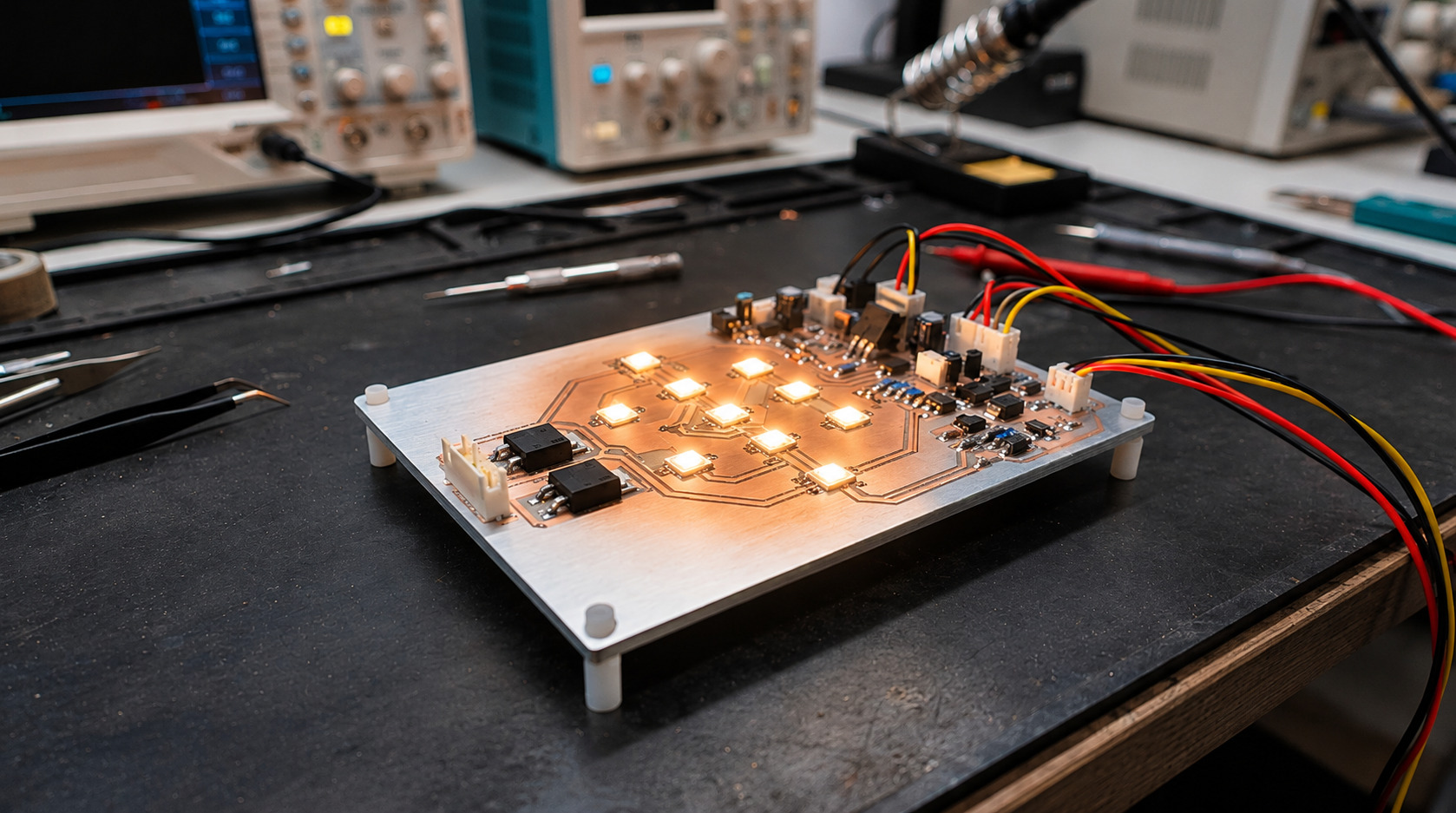
Discover how metal core PCB design improves heat dissipation, manages high-power components, and supports reliable PCB performance in LED lighting, power electronics, and industrial applications.
Metal core PCB design refers to designing circuit boards with a metallic substrate. Usually aluminium substrates are used allowing for excellent heat dissipation. They are required when parts on your PCB can no longer be cooled within a safe temperature using the FR4 material. This guide will explain when this occurs and how your design will be changed.
This is one of the most important considerations when planning a metal core PCB design.
What is metal core PCB design?
Metal core PCB design is the layout of a board that sits on a metal base instead of fiberglass. The metal pulls heat away from components and spreads it out.
A metal core PCB (MCPCB) stacks three layers:
- Copper circuit layer
- Thin dielectric layer. Provides insulation however allows heat to flow.
- Metallic base. Usually aluminium or copper.
As this PCB is constructed using an aluminium base it acts as a self-contained heatsink. As such a good metal core PCB design begins with considering the heat dissipation before the circuit itself.
How much better is MCPCB’s thermal performance?
FR4 has a thermal conductivity of around 0.3W/mK whereas MCPCB’s usually have a thermal conductivity of between 1-4W/mK for the dielectric. This can be seen to be between 3-10x better for most designs depending on the grade.
- FR4 ~ 0.3W/mK
- MCPCB Dielectric ~ 1-3W/mK
- Aluminium Base ~ 200W/mK
- Copper Base ~ 385W/mK
As the thermal distance of heat from the power LED is less for MCPCB’s. The heat travels through a 75-100micron thick dielectric and then into the aluminium. Whereas on FR4 the 1.6mm board is the distance.
These figures will depend on the supplier and grade. Always check the datasheet for exact figures.
Thermal performance is a major factor in metal core PCB design.
Why is thermal management so important in LEDs and Power Electronics?
Electronic components can have a shorter operating lifespan when exposed to excessive temperatures. LEDs are much cooler to the touch than traditional bulbs but can still produce a large amount of heat.
Some quick facts:
- Around 75-85% of the energy powering your LED converts to heat. (US DOE via Digi-Key.)
- Thermal Management is usually the number 1 most important factor affecting LED lifetime (ENERGY STAR)
- LED Lifetime refers to the point where the light output drops by 30%. This will happen quicker if the component is running hotter (ENERGY STAR)
- For white LEDs to retain over 80% of their light the junction temperature should remain below 100C.
- Power Converters and Motor Drivers also suffer from this.
When should I use Metal Core PCB?
Consider an MCPCB when components generate more heat than conventional FR4 boards can effectively dissipate using thermal vias, heatsinks, or airflow.
Metal core PCB design can be a practical and cost-effective solution when conventional FR4 boards struggle to manage heat effectively.
Look out for the following:
- High power LEDs or tightly packed LED arrays
- Hot MOSFET’s, Regulators or Motor Drivers under load.
- Thermal vias taking up space.
- Dimming, colour shift or early failures.
- Fully sealed enclosures with no airflow.
- Heat and vibration. E.g. Automotive and Industrial Equipment.
From one vendor (AtlasPCB) a 1.6mm FR4 board would have around 70C/W Per cm2. An aluminium MCPCB will have around 6-15C/W.
FR4 is a great choice of board but is a poor heat conductor. However due to its cost it is still the ideal choice for low power and cost sensitive designs.
Metal core PCB design is particularly useful for high-power applications.
Where are metal core PCB designs most used?
When you require high power and a small PCB.
- LED Lighting
- Power Supplies
- DC-DC Converters
- Motor Drives
- Inverters
- Automotive
- Industrial Control Equipment
If your board is running hot during testing you are in the right area.
Metal core PCB design supports efficient heat management in these applications.
What changes in the design process?
The substrate, stack up, layout and mechanical design will all change. With the thermal path being considered first and signal routing second.
How do you pick the dielectric?
As the dielectric will determine the maximum thermal capability of your board, care should be taken to ensure the correct conductivity and thickness are chosen. Thinner dielectrics will provide better heat transfer but will have lower breakdown voltages.
- Common choices for LEDs under 60v are 75-100microns with 1.5-2.0W/mK conductivity.
- For power electronics above 100v the dielectric will be around 150-200microns.
- Ensure the breakdown voltage meets your operating voltage with some room to spare.
How many layers do you need?
Most metal core PCB designs will be single or double layered. There are multi-layer metal core PCB’s available but in most cases they are not required. They should be used if you have heavy heat and compact routing.
Where should the hot parts go?
Metal core PCB design makes component placement easier. Place your LEDs, MOSFETs and any heat sources directly on top of the metal base. Ensure plenty of copper is used.
As the metal is on the bottom it will take care of heatsinking and thermal vias are usually not required. Be sure to place any sensitive controllers and sensors away from the hottest area.
What about the mechanical side?
No solder mask or finish is applied to the metal side. A robust metal core PCB design will take this into account from the very beginning. Plan out how the PCB will be bolted to the chassis.
Adding thermal interface material will ensure the heat is transferred across the joint. Using 3D PCB design can help with this. A good 3D PCB design will help identify clashes. Having a 3D representation of your circuit design will help identify if the heatsink will fit, connector height and enclosure clearance.
Aluminium core or Copper core?
Aluminium is generally the preferred material for most custom PCB design applications. It provides a good balance of cost, weight and thermal performance. Both materials are suitable for metal core PCB design.
Choose your material depending on the power. Copper has better thermal conductivity so is ideal for extreme power designs, however it will be more expensive and heavier.
What mistakes should you avoid in metal core PCB design?
- Choosing a material based purely on price. No target for thermal resistance.
- Choosing a thin dielectric without considering the voltage rating.
- Designing your board without considering thermal performance.
- Skipping a pcb design manufacturing review before files go to the fabricator
- Forgetting to consider high frequency requirements. Performance will be slightly worse than FR4.
How does Rhosigma approach metal core PCB design?
Based in Thane, Maharashtra our PCB Design team can provide schematic design, layout and manufacturing support for industrial products.
Typically our process would be:
- Consider your power, temperature and enclosure constraints.
- We provide electronic PCB design to produce a stack up and layout using our experience with pcb design and development of industrial boards.
- Create files for manufacturing. Clean data for your fabricator.
Whether you need PCB design and development from scratch or an existing product with custom PCB design, we will be taking into account the thermal requirements right from the start. We also offer custom printed circuit board design for products used in harsh industrial conditions. We provide services for PCB design and development including circuit board development for LED lighting and power electronics/motor control applications.
We also offer circuit design pcb design service and prototype development all under one roof.
Looking for pcb board design local to you? Share your project requirements with our team and request a quote.
FAQs
What is a metal core PCB?
A PCB with an aluminium or copper base. The board has a thin thermal dielectric to allow heat to be removed from components.
What is the difference between a metal core PCB and FR4?
FR4 is a fibreglass-based PCB with poor thermal properties. The metal core PCB has a thin dielectric to allow heat to flow through to the metal.
How much better is the thermal performance of an MCPCB?
The dielectric usually has a conductivity between 1-3W/mK. FR4 has a conductivity of around 0.3W/mK. This can be seen to be between 3-10x better.
Aluminium or Copper?
Aluminium is suitable for most designs. Copper is only suitable for extreme heat loads.
Can thermal vias be used on FR4 instead of metal core?
They can however will take up routing space and will not be as good as metal core for thermal resistance.
When should I choose metal core PCB design?
When your components can no longer be cooled within a safe temperature using heatsinks, vias or airflow.
Seek Help from Experts with Metal Core PCB Design
Do you need assistance with metal core PCB design for your industry? Provide us with your metal core PCB design requirements, electrical parameters, and operating conditions so that our experts can assist you with your project needs.